Overview
EDGE setup and configuration requires appropriate planning. Once specific project needs have been determined, EDGE can be configured by EQuIS administrators to assist field crews. By configuring EDGE for specific field events, field crews can operate more efficiently and uncertainty with data collection can be minimized.
Only the tabs/forms that are required for the specific field event should be visible to field crews, and any tabs/forms that would never be applicable to the field event should not be available. For example, the Well Construction tab would never be applicable for a surface water sampling event. Other configuration options can include grouping data, creating data range checks, and adding enumerations.
Specific actions to set up and configure EDGE include the following:
•Populate EDGE-related EQuIS tables
•Export field EDD templates
•Create the reference value file (*.rvf)
•Set EDGE options
•Arrange and configure tabs in EDGE
•Configure EDGE forms
Exercise Scenario
Field crews are preparing to collect the requested samples and perform field activities for the new PFOA Project. We need to first configure EDGE for the new site and then generate and provide the appropriate files to the field crews to make their field sampling event simple.
|
Learn to setup EDGE-related data in EQuIS Professional and how to configure EDGE for specific field events. |
|
Exercise Objectives |
•Configure EDGE with the Application Options Menu
•Show or Hide EDGE Format Tabs
•Modify EDGE Forms
•Understand the EDGE Configuration Plugin
•Configure COC Templates
•Populate EDGE-Related Tables in EQuIS Professional
•Generate Field EDD Templates with EQuIS Professional
•Manage Reference Value Files for EDGE
Skills, Software and Permissions Required
•Access to a device (laptop, tablet) with Windows XP or higher and EDGE v6.0 or higher
•.NET Framework 4.0 or higher
•EQuIS Professional v6.6 or higher must be installed on the workstation
•Read/write permissions are required for the desired facilities
|
If EDGE_6.6_Training.zip was already installed and extracted, make a copy of the entire EDGE_6.6._Training directory and rename the copied directory to EDGE_PFOA_Training. |
|
Objective: Configure EDGE with the Application Options Menu |
The Application Options Menu allows EDGE to be configured for different workflow and personal preferences. Available options include appearance, COC, EQuIS database connection, EDD backup options, EDD options, EDP export, field EDP, file attachment, form printing, GeoWizard, image tabs, label printing for bottles, location chooser, logging, persistence, sensors, task chooser, user interface, and working directories.
A limited number of options will be examined in this appendix. View the complete purpose of the application settings in the EDGE Options menu by visiting https://help.earthsoft.com/6.6/edge/index.htm?application-options.htm.
Tasks
•Set Up Auto Save and EDD Backup Locations
•Set Default Templates and Working Folders
•Define Autofill Persistence
Set Up Auto Save and EDD Backup Locations
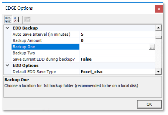
EDD backups are EDD duplicates that EDGE saves at a pre-determined interval. The Auto-Save time interval and the backup locations are set within the EDGE Options window. The second backup location is provided to allow a removable data storage device, such as an SD card, to be used.
1.Launch a previously installed version of EDGE.
For this exercise, launch the Start_EDGE.exe found in the EDGE_PFOA_Training directory.
2.To set EDGE Configuration Options, click on the EDGE Application Menu ![]() and select the Options button. The EDGE Options window will open.
and select the Options button. The EDGE Options window will open.
3.In the EDD Backup section, set the Auto Save Interval to the desired number of minutes, or set to 0 to turn off the Auto Save.
For this exercise, set the Auto Save Interval to 5 minutes.
4.In the Backup One field, select ![]() in the field and then browse to the desired location where a backup of the Field EDD should be saved.
in the field and then browse to the desired location where a backup of the Field EDD should be saved.
5.In the Backup Two field, select ![]() in the field and then browse to the desired location where a second backup of the Field EDD should be saved.
in the field and then browse to the desired location where a second backup of the Field EDD should be saved.
Set Default Templates and Working Folders
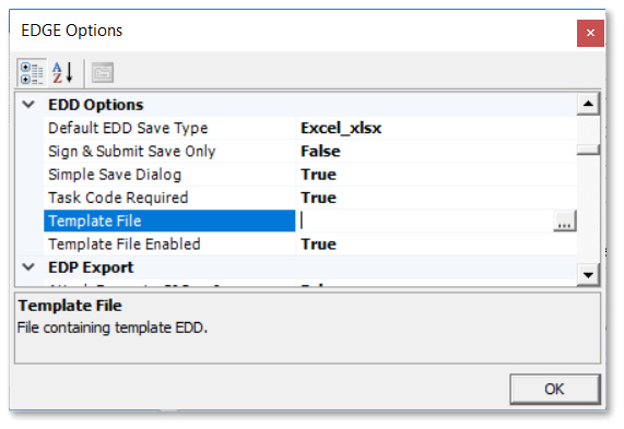
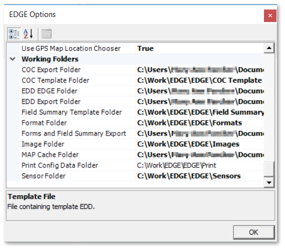
A pre-configured EDD can be used as a Template EDD. Working folders define the default folders for COC Export Folders, COC Template Folders, EDD Folders, Format Folders, Image Folders, and Sensor Folders.
1.Scroll to the EDD Options section in the EDGE Options window, and select ![]() in the Template File input box and navigate to the folder and file.
in the Template File input box and navigate to the folder and file.
2.Set Template File Enabled to True.
3.Scroll to the Working Folders section in the EDGE Options window.
4.Enter in the file path for the default folder for any of the potential Working Folders
(such as the Format Folder).
Set the Autofill Persistence
When the “Save Autofill Values” option is set to True, values entered in Autofill persist when EDGE is closed and re-opened. This is especially useful when field crews are working on the same project or site every time they use EDGE—no need to enter the same information over and over. (Otherwise, Autofill only persists during an individual session.)
1.Scroll to the Persistence section in the EDGE Options window.
2.From the Save Autofill values field, set the value to True.
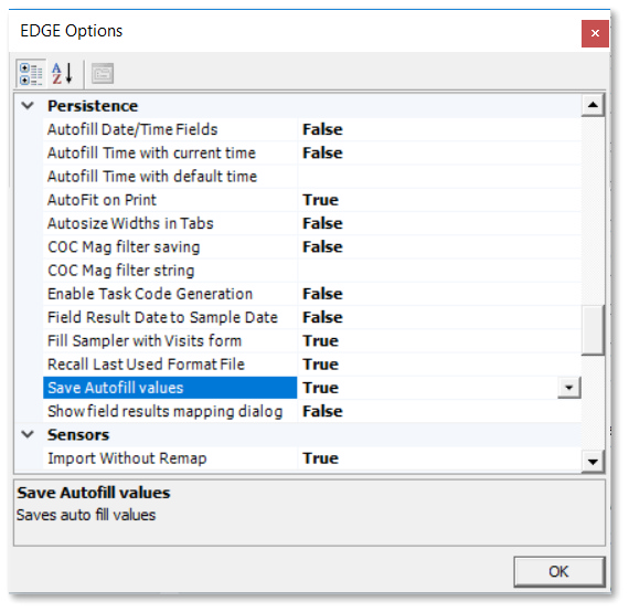
3.Select OK to exit the EDGE Options window.
|
Objective: Show or Hide EDGE Format Tabs |
Set the tabs that will be visible for the EDGE Format. The selected tabs will remain persistent from one EDGE session to another.
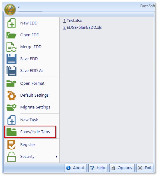
1.Select the EDGE Application Menu ![]() and select Show/Hide Tabs.
and select Show/Hide Tabs.
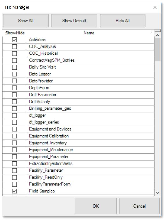
2.The Tab Manager window will open displaying a list of available tabs. Check (to show) or un-check (to hide) the desired tabs.
For this exercise, since we will be collecting Groundwater samples at the PFOA Project, we need to hide the surface water related tabs and show the groundwater related tabs. Un-check the Activities, Field Samples, Location and SW tabs. Check the GW and WL Form tabs.
3.Select the OK button to exit the Show/Hide Tabs screen.
4.Note that the tabs may be rearranged into the desired order by dragging and dropping the tabs. Re-order the visible tabs as desired.
For this exercise, change the positions of the WL Form and GW tabs so the GW tab is listed first.
|
Objective: Modify EDGE Forms |
Most of the out-of-the-box EDGE Forms may be modified and configured to fit the exact needs of the project. Any modifications are preserved from EDGE session to EDGE session, so the configuration only needs to be completed once. Modifications made to an individual form are local to that form, and those changes are not applied to the other forms.
For information on making global changes to fields that appear in multiple forms, see the next section on the EDGE Configuration Plugin. The next section also discusses how to rename the tabs and forms.
Tasks
•Turn Off Form Sections
•Turn Off Individual Fields in Forms
•Rename Fields in Forms
•Set Default Values for Fields in Forms
•Rename Form Sections
Turn Off Form Sections
1.Select the desired form to modify.
For this exercise, select the GW form.
2.Select the Form ribbon and then the Display ![]() drop-down from the View group.
drop-down from the View group.
3.Single-click any checked items on the Display drop-down to turn off those sections on the form.
For this exercise, single-click on Lab_COC_analysis, Field Results, Field Results Extra, Containers and Field Batch Partner to turn off those sections. Notice how the GW form changes as the sections are turned off.
4.To turn off fields in a specific section, select the Setup ![]() drop-down from the View group on the Form ribbon and select the desired section.
drop-down from the View group on the Form ribbon and select the desired section.
5.Un-check the specific fields that should be turned off and Save the changes. Note that sections with only un-checked fields no longer appear on the form.
For this exercise, un-check all of the fields in the Equipment, Water Level Purge and Volume Purge sections and Save the changes. Water Levels will be captured separately on the WL Form tab. Notice how the GW form changes as the fields are turned off.
|
Turn off an entire section by un-checking all the fields in that section. |
Turn Off Individual Fields in Forms
1.Select the Setup ![]() drop-down from the View group on the Form ribbon and select the desired section.
drop-down from the View group on the Form ribbon and select the desired section.
2.Un-check the specific fields that should be turned off and Save the changes. Note that the un-checked fields no longer appear on the form.
For this exercise, select the Location section and un-check the PROJECT, PROJECT_DESC, and ALERT_PURGE_CRITERIA fields and Save the changes.
3.Repeat steps 1 and 2 for fields in other sections.
For this exercise, select the Sample section and un-check the SYS_LOC_CODE, ARRIVAL_START_TIME, FILTERED_YN, ICE_IN_COOLER, EQUIPMENT_CODE, and EQUIPMENT_CAL_DATE fields. Notice how the GW form changes as the fields are turned off.
Rename Fields in Forms
1.Rename a display caption on the form by selecting the Setup ![]() drop-down from the View group on the Form ribbon and then the desired section.
drop-down from the View group on the Form ribbon and then the desired section.
For this exercise, select the Location section.
2.Single-click on the Column to be modified.
For this exercise, select the SYS_LOC_CODE column.
3. In the Display Text field at the bottom of the Data Section form, enter in the preferred caption.
For this exercise, enter "Well ID" as the preferred caption.
4.Select the Save button to examine the changes to the form.
Set Default Values for Fields in Forms
1.Select the Setup ![]() drop-down from the View group on the Form ribbon and then the desired section.
drop-down from the View group on the Form ribbon and then the desired section.
For this exercise, select the Sample section.
2.Set a Default value for a field by single-clicking on that Column to highlight it.
For this exercise, highlight the SAMPLE_MATRIX_CODE Column.
3.In the Default field at the bottom of the Data Section form, enter in the desired default value. Note that this default value will be used only on this form.
For this exercise, enter WG as the default value.
4.Select the Save button to examine the changes to the form.
5.Repeat steps 1-4 for any additional default values.
For this exercise, select the SAMPLE_TYPE_CODE Column and enter N as the default value.
|
Remember that any default values need to align with any reference value restrictions on that specific field. |
Change the Order of Form Sections
1.To change the order of the sections on a Form, select the the Display ![]() drop-down from the View group and then select Order.
drop-down from the View group and then select Order.
2.Move the sections up or down with the arrows at the bottom of the Control Order window, as desired. Note that all sections are shown, including those turned off.
For this exercise, move the Sample section so that it is above the Weather section.
3. Select the Close button to examine the changes on the Form.
Rename Form Sections
1.To rename a section on a Form, select the Setup ![]() drop-down from the View group on the Form ribbon and then the desired section.
drop-down from the View group on the Form ribbon and then the desired section.
For this exercise, select the Climate Conditions section.
2.In the Display Name at the top of the Data Section window, rename the section as desired.
For this exercise, enter "Weather Observations" into the Display Name field.
3.Select the Save button to return to the form.
Note that there are multiple fields on the Form with drop-down values, and some fields on the Form are also required. The Form title and the Tab name may also need changes. These additional configurations may be made in the EDGE Configuration Plugin, discussed in the next section.
The configuration tool allows the user to edit the standard configuration of EDGE, including captions, EDP export options, enumeration values, format sections, and tab settings.
Tasks
•Edit Virtual Captions
•Define Enumeration values
•Configure the Format Sections
•Change the Tab Settings
Edit Virtual Captions
Three virtual fields appear throughout EDGE: Alerts, Location_Name, and Time. These fields are referred to as "virtual" since they appear in the EDGE user interface (for ease of reference for the user), but they are not present in the EDGE format. These captions cannot be edited within the Format Section of the configuration tool.
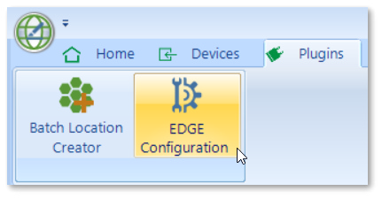
1.To access the EDGE configuration tool, navigate to the Plugins tab ribbon and click on EDGE Configuration. The EDGE Configuration window will open.
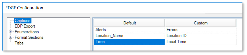
2.Select the Captions section.
3.Add the desired caption to the Custom column for each field.
For this exercise, enter "Errors" for ALERTS, "Location ID" for LOCATION_NAME, and "Local Time" for TIME.
4.Select the Save button.
Define Enumeration Values
Enumeration values are stored within the [Format]-enum.xml file, allowing any field to be setup as a drop-down from the enumeration. Values listed in a drop-down menu that references an enumeration will display in the order that is set in the configuration tool. This allows more commonly used values to be at or near the top of the list, for ease of access in EDGE.
|
Use of commas (,) and blank spaces in enumeration values can cause drop-down menus referring to enumerations to fail in EDGE. |
1.Expand the Enumerations section of the EDGE Configuration window.
2.Select the enumeration to be edited within the left pane, under the Enumerations node. The enumeration values for the selected list are displayed in the right window.
For this exercise, select the precipitation enumeration.
3.To add a new value, click the Add to List button in the Enumeration Values frame. In the Enumeration window, enter the desired text and then select the OK button.
For this exercise, add a value of "showers" to the list.
4.To edit a value, highlight the desired enumeration from the list and click the Edit button in the Enumeration Values frame. Change the text as desired and select the OK button.
5.To delete a value, highlight the desired enumeration and click the Delete button in the Enumeration Values frame. A warning message will be displayed. Select the Yes button to continue with the deletion.
6.To edit the display order of the enumerations, select a value from the Enumeration Values list and use the Value Up and/or Value Down button to move the value to a different position on the list.
For this exercise, move showers so it is listed directly below rain.
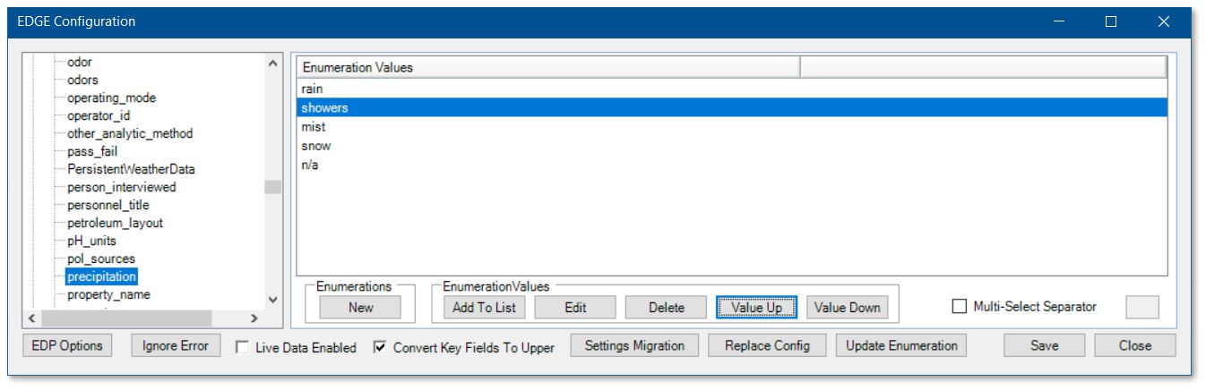
7.Select the Save button to save changes.
|
Instead of supplying drop-down lists on EDGE fields, some enumerations will change functions of EDGE depending on which value is listed first. Examples of these kinds of enumerations are those related to the Sample ID Builder. |
Configure the Format Sections
Format Sections in the EDGE Configuration window displays all sections that are available within the format. Only format sections assigned to group "field" in the format .xse/.xsd are accessible in the configuration tool. For each format section, the following can be edited:
•Caption
•Default value
•Lookup and lookup options
•Required fields
•File attachment options
|
Note that changes made within the Format Sections are global within EDGE. For example, making a field required in the Format Section will make that field required in all instances of |
1.Expand the Format Sections node in the EDGE Configuration window.
2.Select the desired format section within the left pane. There are two tabs—one for editing the columns within the format section and the other for editing the file attachment properties. Any default format settings are highlighted in red text, and any that have been overridden are in black text.
For this exercise, select the FieldSample_v1 section.
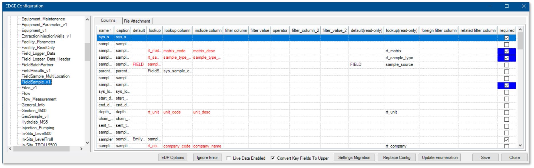
3.Edit the following options, as desired:
Column |
|
|---|---|
Caption |
The caption column allows a caption to be set for the selected column name. This caption will be displayed when the column is shown. |
Default Value |
This sets the default value to insert within the column when a new record is created. |
Lookup |
This allows a column to be set as a lookup to the reference file or an enumeration list and gives the ability to filter the chosen lookups. |
Required |
A field within the opened format can be set as required within EDGE by checking the required check box for the column. This only works for setting fields as required; it will not remove a required property from the format. |
For this exercise, note the precipitation Column already has a lookup of precipitation. Additionally, the Sampler column has been made required. Make any other modifications, as desired.
|
Note that fields highlighted in blue are required by EQuIS and the EDGE format and may not be changed. |
4.To enable a format table to support file attachments within EDGE, select the File Attachment tab.
5.Select the File Attachment Enabled check box.
6.Set values for the "Place type," "Place code," and "Place sub-code" that will be entered within the DT_FILE record when a file is attached.
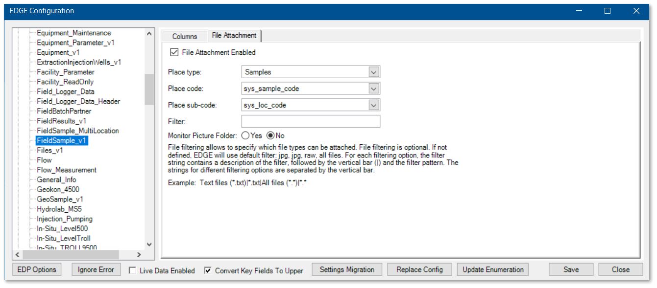
7.Select the Save button to save changes.
Change the Tab Settings
This section in the EDGE Configuration window allows the display name of tabs to be edited and to choose whether or not they appear in the Show/Hide Tabs option of EDGE.
1.Select the Tabs section in the EDGE Configuration window.
2.To edit the display name of a tab, edit the value in the text box of the Tab Caption column.
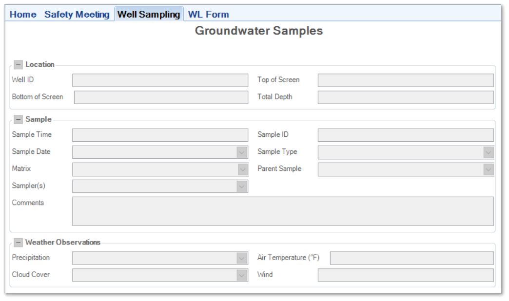
For this exercise, find the FieldSampleForm tab and change the Tab Caption to "Well Sampling".
3.To edit the title that appears in the header of a form, edit the value in the Form Title column.
For this exercise, change the Form Title of the FieldSampleForm to "Groundwater Samples".
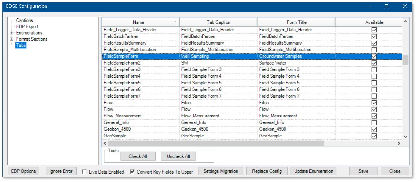
4.The “Available” check box may be used to make the tab visible or not visible in the Tab Manager. Making a tab unavailable also means that EDGE will not load the tab/form in the background on start up. Performance and start up time in EDGE can be improved by reducing the number of available tabs.
5.Select the Save button to save all changes to the Format.
6.Select the Close button to exit the EDGE Configuration window and return to the main EDGE window. EDGE will restart to apply the new configuration.
|
Objective: Configure COC Templates |
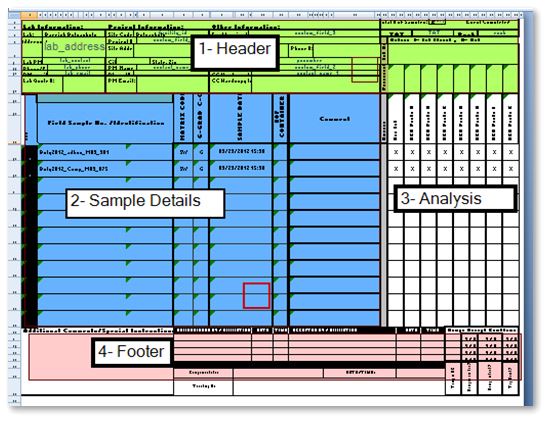
EDGE can create chain of custody forms. The export relies on the use of an Excel COC template file to convert data exported from an EDGE Field EDD into a COC form. A template file is supplied by default with EDGE and SPM and can be configured. The "Setup" sheet in the "COC_Template" file in EDGE can be used to set default values and/or build a custom COC template without editing the VBA code in Microsoft Excel. The COC in EDGE consists of four parts: 1) header, 2) sample details, 3) analysis, and
4) footer.
1.Browse to the current COC template file, typically in \EDGE\COC Template and open the template file.
2.Select the Setup tab within the COC template file.
3.As desired, change the values in the general section, header and footer, sample details, and analysis.
4.Select Save As and save the custom template file under a different name in the same working folder.
|
Objective: Populate EDGE-Related Tables in EQuIS Professional |
Plan, organize, and check field data by creating groups of field activities and field measurements and by establishing data range checks for field measurements using either action levels or stabilization criteria. Once these groups and range checks are available in EQuIS, they can be used in EDGE.
|
This exercise requires changes to data tables, system tables, and reference tables. Each EQuIS database has only one set of reference values for all of the facilities in that database. Hence, this exercise is recommended for EQuIS Power Users and should only be used with permission from the Database Administrator to add reference values to the EQuIS database. |
Tasks
•Create Groups for Field Results
•Create Groups for Custom Activity Lists
•Create Range Checks in Field Results
Create Groups for Field Results
1.Launch EQuIS Professional and select the desired facility.
For this exercise, select the PFOA Project facility and the Premier Data & Graphics license.
2.Select Reference Tables ![]() from the Open group on the Home ribbon.
from the Open group on the Home ribbon.
3.Open RT_ANALYTE and ensure the desired analytes are present (or enter them as necessary).
4.Select Groups ![]() located in the Edit group of the Home ribbon.
located in the Edit group of the Home ribbon.
5.Single-click on the Analyte group type to highlight it and select New> New Group ![]() from the Groups toolbar to add a new Analyte Group. On the Group Details tab, enter the desired GROUP_CODE and select the Save button.
from the Groups toolbar to add a new Analyte Group. On the Group Details tab, enter the desired GROUP_CODE and select the Save button.
For this exercise, enter "Field_SQM_<your initials>" into the Code field.
6.Set the GROUP_TYPE to “Field”. (The Field Results tab in EDGE will only display Analyte Groups with “Field” in group_type.)
7.Add any other desired information.
For this exercise, enter "Field Parameters" for the Description and set the Facility ID to the new PFOA Project ID.
8.On the Group Members tab, add the desired Group Members from the list of available members.
For this exercise, add Conductivity, DO, ORP, pH, Field Salinity, Water Temperature, and Field Turbidity. To easily find these members, enter FLD in the CAS RN search box (turn Filters ![]() on if needed).
on if needed).
9.Select the Save ![]() icon on the Groups tab toolbar to save the new information.
icon on the Groups tab toolbar to save the new information.
Create Groups for Custom Activity Lists
1.Select Data Tables ![]() from the Open group on the Home ribbon.
from the Open group on the Home ribbon.
2.Select System Tables ![]() from the side bar on the Open window. Open the ST_GROUP_TYPE table.
from the side bar on the Open window. Open the ST_GROUP_TYPE table.
3.Add a row to the ST_GROUP_TYPE table and enter “SPM_ACTIVITY_<your initials>” in the GROUP_TYPE field. Select the Save ![]() icon on the ST_GROUP_TYPE tab toolbar to save the change.
icon on the ST_GROUP_TYPE tab toolbar to save the change.
4.Select Reference Tables ![]() from the Open group on the Home ribbon and open RT_LOCATION_PARAM_TYPE.
from the Open group on the Home ribbon and open RT_LOCATION_PARAM_TYPE.
5.Add rows in RT_LOCATION_PARAM_TYPE for each parameter to be measured or observed during the Activity. The PARAM_DESC will be displayed in EDGE when the Activity Form is selected.
For this exercise, enter "Precip_YN" for the PARAM_CODE and "Is there Precipitation" for the PARAM_DESC.
6.Save ![]() the changes to RT_LOCATION_PARAM_TYPE.
the changes to RT_LOCATION_PARAM_TYPE.
7.Select Reference Tables ![]() from the Open group on the Home ribbon and open RT_GROUP.
from the Open group on the Home ribbon and open RT_GROUP.
8.Add a row to RT_GROUP and enter:
a.GROUP_CODE = A code for the Activity Form group
b.GROUP_TYPE = SPM_ACTIVITY_<your initials>
c.GROUP_DESC = The description, which will be displayed in the Activity Form drop-down list in EDGE.
For this exercise, enter "PFOA Weather" for the GROUP_CODE, "SPM_ACTIVITY<your initials>" for the GROUP_TYPE, "PFOA Project Weather" for the GROUP_DESC, and set the FACILITY_ID to the new PFOA Project ID.
9.Save ![]() the changes to RT_GROUP.
the changes to RT_GROUP.
10.Select Reference Tables ![]() from the Open group on the Home ribbon and open RT_GROUP_MEMBER.
from the Open group on the Home ribbon and open RT_GROUP_MEMBER.
11.Add a row to RT_GROUP_MEMBER for each row added to RT_LOCATION_PARAM_TYPE above and enter:
a.GROUP_CODE = The code for the Activity Form group entered above
b.MEMBER_CODE = PARAM_CODE from RT_LOCATION_PARAM_TYPE
c.MEMBER_TYPE = “SPM_ACTIVITY”
d.REMARK = A field type from the following:
i.Blank or EDGE_TEXT= Text (up to 255 characters)
ii.EDGE_Integer= Integer (1,2,3,4,5)
iii.EDGE_Decimal=decimal (1, 1.1, 1.22)
iv.The List Name from the format enumeration (…-enum.xml) file (e.g. enter “Colors” if an enumeration list exists for colors with this name)
For this exercise, enter "PFOA Weather" for the GROUP_CODE, "Precip_YN" for the MEMBER_CODE, and "SPM_ACTIVITY" for the MEMBER_TYPE. Repeat for other location parameters, as desired, such as "Cloud Cover" and "Wind Speed".
Create Range Checks in Field Results
1.Select Action Levels ![]() from the Edit group of the Home ribbon.
from the Edit group of the Home ribbon.
2.Select Add New Type/Code> New Action Level Code ![]() from the Action Levels toolbar to add a new Action Level Code. On the Action Levels Code Details tab, enter the desired Code and then select the Save button to activate the tab. Enter other information as needed.
from the Action Levels toolbar to add a new Action Level Code. On the Action Levels Code Details tab, enter the desired Code and then select the Save button to activate the tab. Enter other information as needed.
For this exercise, highlight "Irrigation Waters" and then add the new Code. Enter "PFOA Field Parameters <your initials>" for the Code. Select the Save button.
3.On the Action Level Parameters tab, add the desired field parameters from the Available Parameters list (presumably including the same parameters as in the Field Result Group set up previously).
For this exercise, add Temperature and pH. To easily find these members, enter FLD in the CAS RN search box (turn Filters ![]() on if needed).
on if needed).
Select a MATRIX of WS, a FRACTION of N and an ANALYTIC_METHOD of Field Measure for both parameters.
For Temperature, set a UNIT of deg C and for pH, set a UNIT of SU.
4.The next step will depend on which type of action level are desired: Field Alerts or Stabilization Criteria (with or without Minimum Purge Volume calculations).
Action Levels for Field Alerts
A.Enter values in WARNING_LEVEL and WARNING_LEVEL_MIN fields that describe the maximum and minimum allowable values (respectively) for the parameter.
B.Set the UNIT for the parameter.
For this exercise, for pH, enter 4 for the WARNING_LEVEL_MIN and 10 for the WARNING_LEVEL. For Temperature, enter 1 for the WARNING_LEVEL_MIN and 25 for the WARNING_LEVEL.
Action Levels for Stabilization Criteria
Action Levels to determine when a reading is stable may also be setup. For further information, see this Online Documentation article.
5.Select the Save ![]() icon on the Action Levels tab toolbar to save the new information.
icon on the Action Levels tab toolbar to save the new information.
6.Select Reports ![]() from the Open group on the Home ribbon.
from the Open group on the Home ribbon.
7.Select the EDGE Setup Advanced Field Alerts and Action Levels report and click on the Open button. The EDGE Setup Advanced Field Alerts and Action Levels report facilitates the configuration of the action levels. Run the report to link location(s), MAG(s) and Action Level(s) together. Already established criteria may be added to later by entering the same criteria text in the Action Level Criteria and selecting new locations, MAGs or Action Levels.
8.Select the desired parameters.
Parameter Description |
|---|
Action Level Criteria: Enter the text (criteria) that will be used to link locations to MAGs and |
Locations: Choose individual locations and/or groups of locations. |
Method Analyte Group(s): Choose from MAGs with Type = Field. |
Action Level> Field Alerts: Choose from action levels where action level type does not contain “purge”. |
Action Level> Stabilization Criteria: Choose from action levels where action level type contains “purge”. |
Add: Add Action Level Criteria. Remove: Remove Action Level Criteria. |
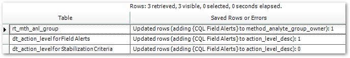
The criteria text entered in the Action Level Criteria parameter is written to the following fields when the report is run with selections made as indicated:
•Locations: DT_LOCATION.ALERT_PURGE_CRITERIA
•MAGs: RT_MTH_ANL_GROUP. METHOD_ANALYTE_GROUP_OWNER
•Action Levels: DT_ACTION_LEVEL.ACTION_LEVEL_DESC
For this exercise, enter "PFOA Field Alerts" for the Action Level Criteria, select the Method Analyte Group of Field, select the new PFOA Field Parameters <your initials> as the Action Level> Field Alert, and ensure that Add is selected under the Add or Remove parameter.
9.Select the Go ![]() button on the Report toolbar to run the report.
button on the Report toolbar to run the report.
10. The report will return results that display which fields were updated.
|
Objective: Generate Field EDD Templates with EQuIS Professional |
1.Copy the EarthSoft.Reports.Library.40338.dll from the Reports directory under the EDGE installation folder into the EQuIS Professional folder (C:\Program Files\EarthSoft\EQuIS).
2.Launch EQuIS Professional and select the desired facility.
For this exercise, select the PFOA Project facility and the Premier Data & Graphics license.
3.Select Reports ![]() from the Open group on the Home ribbon.
from the Open group on the Home ribbon.
4.Select the EDGE Field EDD report and click on the Open button.
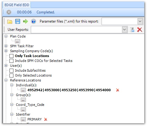
5.Select the desired parameters. The Format will be set to EDGE by default.
For this exercise, un-check the Only Task Locations box and select any desired Reference Locations to be included in the Field EDD.
6.Select the Go ![]() button on the Report toolbar to run the report. The EDGE EDD opens in Microsoft Excel. The default file name will be formatted as EDGE_Facility ID_[Plan Code, if included]_Current Date and Time.
button on the Report toolbar to run the report. The EDGE EDD opens in Microsoft Excel. The default file name will be formatted as EDGE_Facility ID_[Plan Code, if included]_Current Date and Time.
7.Save the EDGE EDD file to the desired location and rename as appropriate.
|
Objective: Manage Reference Value Files for EDGE |
It is imperative that the field crews use a reference value file that contains the correct values. If the values used in EDGE do not match the values in EQuIS, submission of EDDs will fail. Whenever reference values are changed in EQuIS, a new reference value file must be generated for use in EDGE and supplied to the field crews.
Tasks
•Create a New Reference Value File in EQuIS Professional
•Open and Point to a New Reference Value File in EDGE
Create a New Reference Value File in EQuIS Professional
1.Launch EQuIS Professional and select the facility where the Reference Values for the site are stored.
For this exercise, select the PFOA Project facility and the Premier Data & Graphics license.
2.Select EDP ![]() from the Import group on the Home ribbon.
from the Import group on the Home ribbon.
3.Load the EDGE.xse format. (The last format may automatically load. To use a different format, click the Format ![]() from the Open group of the EDP Home ribbon.)
from the Open group of the EDP Home ribbon.)
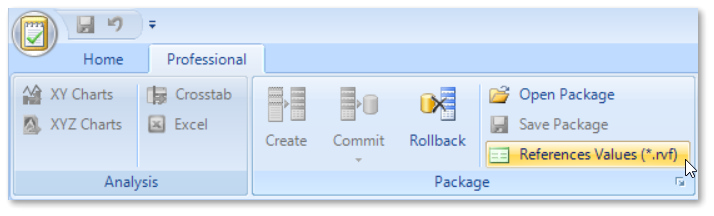
4.Select the Professional tab.
5.Select Reference Values (*.rvf) ![]() from the Package group of the Professional ribbon.
from the Package group of the Professional ribbon.
6.Enter the path where the .rvf will be saved and give the file a descriptive name when prompted.
7.Click the Save button.
Point to a New Reference Value File in EDGE
Upon opening the EDGE format, EDGE checks for the presence of an .rvf.
1.Launch EDGE.
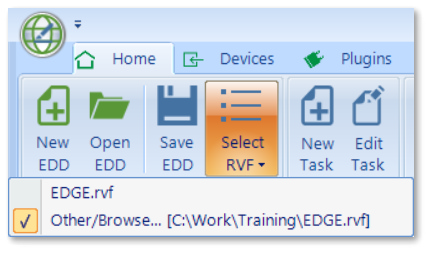
2.Switch to a different .rvf by clicking Select RVF ![]() from the EDD group on the Home ribbon.
from the EDD group on the Home ribbon.
3.The Select RVF tool displays a list of reference value files available in the current format folder, as well as an option to browse to another folder. If the .rvf created in the previous exercise is not listed, select Other/Browse and browse for the .rvf located outside of the current working folder. The selected .rvf will be used each time EDGE is started, unless the file cannot be located.
4.When switching to a different .rvf, EDGE restart is required and performed automatically upon user approval. EDGE will ask to save the current EDD before restarting.